Understanding the basics of a thermostat hookup diagram
What a Thermostat Hookup Diagram Shows
A thermostat hookup diagram is a visual guide that shows how each wire connects your smart thermostat to your HVAC system. These diagrams are essential for anyone installing or upgrading to a smart thermostat, as they help you understand the relationship between your thermostat, the wires, and the heating or cooling equipment in your home. By following the diagram, you can see which wire goes to which terminal, ensuring your system works safely and efficiently.
Why Understanding the Diagram Matters
Modern HVAC systems can be complex, with multiple wires for heating, cooling, air handlers, heat pumps, and even second stage heating or cooling. Each wire is labeled and color-coded, and each terminal on the thermostat or control board has a specific function. Knowing how to read the diagram helps you avoid mistakes, like connecting a wire to the wrong terminal, which could cause your system to malfunction or even damage your smart thermostat.
How the Diagram Helps With Installation
Before you start wiring, it’s important to identify the wires coming from your HVAC system. The diagram will show you where each wire should be connected, whether it’s for power, the common wire, the reversing valve (often the blue wire in heat pump systems), or other functions. This step-by-step guide is crucial for both new installations and when replacing an old thermostat with a smart model.
Types of Systems Covered
Thermostat hookup diagrams can vary depending on your HVAC system. Some diagrams are for basic heating and cooling, while others include more advanced setups like heat pumps, multi-stage heating or cooling, or systems with an air handler. Understanding the diagram for your specific system ensures that your smart thermostat will control your home’s temperature accurately and efficiently.
If you’re just starting out and want to make sure you choose the right thermostat for your needs, check out this guide to choosing the right hot water thermostat. It’s a helpful resource for understanding the basics before diving into wiring diagrams and installation.
Key components and symbols in wiring diagrams
Decoding Symbols and Labels in Thermostat Wiring Diagrams
When you first look at a thermostat wiring diagram, it can seem overwhelming. But once you understand the symbols and labels, it becomes much easier to follow. These diagrams are designed to help you connect each wire to the correct terminal, ensuring your smart thermostat can control your HVAC system efficiently.
- Wires and Color Codes: Most thermostat wires are color-coded for easy identification. For example, the red wire (often labeled R or Rh/Rc) supplies power, while the white wire (W) typically controls heating. The yellow wire (Y) is for cooling, and the green wire (G) operates the fan. The blue wire or C wire (common wire) provides continuous power for smart thermostats.
- Terminals: Each terminal on the thermostat base is labeled to match the corresponding wire. Common labels include Y (cooling), W (heating), G (fan), C (common), O/B (reversing valve for heat pumps), and R (power).
- Symbols: Diagrams use simple symbols to represent components like the air handler, heat pump, or control board. Lines indicate wires, while dots show where wires are connected. Arrows may indicate the direction of current or control signals.
- Stages: Some HVAC systems use second stage heating or stage cooling. These are often labeled as W2 or Y2 in the diagram, showing where additional wires connect for multi-stage systems.
Understanding these elements is crucial for anyone looking to wire a smart thermostat or troubleshoot their system. If you want a deeper dive into the specifics of thermostat wiring, there are comprehensive guides available that break down each wire and terminal in detail.
| Wire Color | Label/Terminal | Function |
|---|---|---|
| Red | R, Rh, Rc | Power (24V) |
| White | W, W1, W2 | Heating (Stage 1/2) |
| Yellow | Y, Y1, Y2 | Cooling (Stage 1/2) |
| Green | G | Fan Control |
| Blue/Black | C | Common Wire (Power for smart thermostats) |
| Orange | O/B | Reversing Valve (Heat Pump) |
By familiarizing yourself with these symbols, labels, and color codes, you’ll be better equipped to read any thermostat hookup diagram, whether you’re installing a new smart thermostat or troubleshooting an existing HVAC system.
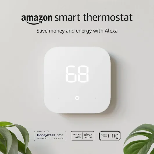
- + Energy saving — advertised to save money and energy
- + Works with Alexa and Ring — integrates with popular smart home platforms
- + Simple 1-pack — single thermostat unit for straightforward replacement
- + Amazon brand — from a well-known smart home ecosystem
Step-by-step guide to reading your smart thermostat diagram
Breaking Down the Thermostat Wiring Diagram
When you first look at a thermostat wiring diagram, it can feel overwhelming. But with a little patience, you can decode what each wire and terminal does. Here’s a practical guide to help you read and use your smart thermostat diagram effectively.
- Identify the labeled terminals: Most diagrams use standard labels for terminals, like R (power), W (heat), Y (cooling), G (fan), C (common), and O/B (reversing valve for heat pumps). These labels tell you where each thermostat wire should connect.
- Match wire colors to functions: While colors can vary, there are common conventions. For example, the red wire usually carries power (R), white is for heating (W), yellow for cooling (Y), green for the fan (G), and blue or black often serves as the common wire (C) for smart thermostats.
- Trace the system connections: The diagram shows how your HVAC system components—like the air handler, heat pump, or furnace—connect to the thermostat. This helps you understand how heating, cooling, and fan control are managed.
- Look for stage heating and cooling: Some systems have multiple stages (first and second stage heating or cooling). These are usually labeled as W1/W2 or Y1/Y2. Make sure your smart thermostat supports these if your system uses them.
- Spot the reversing valve: If you have a heat pump, the O/B terminal controls the reversing valve, which switches the system between heating and cooling modes.
Practical Steps to Use the Diagram
- Turn off power to your HVAC system before starting any wiring work.
- Take a photo of your existing thermostat wiring for reference.
- Compare the wires coming from your wall to the diagram. Match each wire to its labeled terminal on the smart thermostat.
- Check for a common wire (C): Smart thermostats often need a C wire for continuous power. If you don’t see a blue wire or a terminal labeled C, you may need an adapter or a professional’s help.
- Connect each wire to the correct terminal, following the diagram thermostat instructions. Double-check each connection before powering up.
For a more in-depth look at how to interpret specific models, you might find this Blink thermostat wiring guide helpful. It breaks down the wiring process for a popular smart thermostat, with clear visuals and troubleshooting tips.
Remember, the wiring diagram is your roadmap. It shows how your thermostat will control your HVAC system, whether you have a basic heating cooling setup or a more complex heat pump thermostat with second stage features. Take your time, and don’t hesitate to consult a professional if you’re unsure about any step.
Common wiring configurations for smart thermostats
Typical Wiring Setups for Smart Thermostats
When installing a smart thermostat, understanding the most common wiring configurations is essential. The wiring diagram for your thermostat will show how each wire connects to the correct terminal, ensuring your HVAC system operates safely and efficiently. Here’s a guide to the typical setups you might encounter:
- Single Stage Heating and Cooling: This is the most straightforward configuration, often found in homes with basic HVAC systems. You’ll usually see wires labeled R (power), W (heat), Y (cooling), G (fan), and C (common). Each wire connects to its matching terminal on the thermostat.
- Heat Pump Systems: Heat pumps require a few extra connections. In addition to the standard wires, you’ll find an O/B terminal for the reversing valve, which switches the system between heating and cooling. The blue wire is often used as the common wire, but always check your wiring diagram to confirm.
- Multi-Stage Heating or Cooling: Advanced HVAC systems may have second stage heating or cooling for better temperature control. These setups add extra wires, such as W2 for second stage heating or Y2 for second stage cooling. The thermostat wiring diagram will clearly show where these wires should be connected.
- Air Handler and Auxiliary Heat: In some systems, especially those with electric heating, you’ll see additional terminals like AUX or E for emergency heat. These are important for backup heating and are labeled on both the wiring diagram and the thermostat itself.
How to Match Wires to Terminals
Each wire in your thermostat bundle is color-coded and labeled for a specific function. The diagram will help you match each wire to its correct terminal. Here’s a quick reference table for common wire colors and their typical functions:
| Wire Color | Typical Terminal | Function |
|---|---|---|
| Red | R | Power (24V) |
| White | W / W1 | Heating |
| Yellow | Y / Y1 | Cooling |
| Green | G | Fan control |
| Blue or Black | C | Common wire |
| Orange | O/B | Reversing valve (heat pump) |
It’s important to note that wire colors can vary, especially in older homes or custom installations. Always double-check your wiring diagram and the labels on your thermostat terminals before connecting anything. If you’re unsure, consult a professional or refer to the manufacturer’s guide for your specific smart thermostat model.
Troubleshooting wiring issues using the diagram
Identifying Wiring Problems with Your Smart Thermostat
When your smart thermostat isn’t working as expected, the wiring diagram becomes your best troubleshooting tool. Start by double-checking that each thermostat wire is connected to the correct terminal as labeled in the diagram. A single misplaced wire can cause issues with heating, cooling, or even power supply to the thermostat.
- No Power: If your thermostat will not turn on, check the common wire (often the blue wire labeled C). This wire supplies continuous power to many smart thermostats. If it’s not connected or is loose, your device may not power up.
- Heating or Cooling Not Working: Verify that the wires for heating (often labeled W or W1 for first stage heating, W2 for second stage) and cooling (Y or Y1 for first stage cooling, Y2 for second stage) are properly seated in their terminals. For heat pump systems, ensure the reversing valve wire (usually O or B) is correctly connected, as this controls the switch between heating and cooling modes.
- System Runs at the Wrong Time: If your HVAC system starts heating when it should be cooling, or vice versa, check the wiring for the air handler and the heat pump thermostat. The wiring diagram will show which wire controls each function. A swapped wire can cause the system to behave unpredictably.
- Fan Issues: If the air fan doesn’t run, confirm the G wire is connected to the correct terminal. This wire controls the fan relay in most HVAC systems.
Using the Diagram to Trace and Test Connections
Follow the wiring diagram thermostat guide to trace each wire from the thermostat back to the HVAC system. Use a multimeter to test for continuity and voltage at each terminal if you suspect a break or short. The diagram will help you identify which terminal should have power and when, depending on whether you’re calling for heating or cooling.
| Wire Color | Typical Terminal | Function |
|---|---|---|
| Red | R | Power from transformer |
| Blue/Black | C | Common wire (power return) |
| White | W/W1 | First stage heating |
| Yellow | Y/Y1 | First stage cooling |
| Green | G | Fan control |
| Orange | O/B | Reversing valve (heat pump) |
When to Seek Professional Help
If you’ve checked all wire connections according to the wiring diagram and your smart thermostat or HVAC system still isn’t working, it may be time to consult a professional. Some issues, like a faulty air handler or a damaged control board, require specialized tools and expertise. Always prioritize safety and never attempt repairs beyond your comfort level.
Safety tips and best practices for installation
Staying Safe When Installing or Adjusting Your Smart Thermostat
When working with thermostat wiring, safety should always be your top priority. Smart thermostats connect directly to your HVAC system and power supply, so taking the right precautions can prevent damage to your equipment and keep you safe.- Turn off power: Always switch off power to your HVAC system at the breaker before handling any thermostat wire or terminal. This step protects you from electric shock and prevents short circuits in your system.
- Label wires before disconnecting: Use labels or take a photo of your existing wiring configuration. This helps you reconnect each wire to the correct terminal, especially when dealing with multiple wires for heating, cooling, or heat pump systems.
- Use the correct tools: A small screwdriver, wire stripper, and voltage tester are essential. Avoid using makeshift tools that could slip and damage the thermostat or wiring.
- Check for secure connections: Ensure each wire is firmly attached to its labeled terminal. Loose wires can cause intermittent control issues or prevent your smart thermostat from functioning properly.
- Follow the wiring diagram: Refer to the diagram thermostat that matches your specific HVAC system—whether it’s a heat pump, air handler, or multi-stage heating cooling setup. This ensures all wires are connected as required for your system’s features, such as second stage heating or a reversing valve.
- Handle the common wire (C wire) with care: The common wire supplies continuous power to many smart thermostats. Make sure it’s connected correctly to avoid power issues or damage to the thermostat.
- Don’t force wires: If a wire doesn’t fit easily into a terminal, double-check the wiring diagram and the wire’s label. Forcing wires can damage the terminal or the wire itself.
- Inspect for exposed copper: Only the necessary amount of copper should be exposed at the end of each thermostat wire. Excess copper can cause shorts between terminals.
Best Practices for a Smooth Installation
- Read the guide: Before starting, review the installation guide for your smart thermostat and your HVAC system. Each model may have unique requirements for wiring and control.
- Double-check compatibility: Not all thermostats work with every HVAC system. Confirm that your smart thermostat supports your system type, such as heat pump thermostat or multi-stage heating cooling.
- Test before finishing: After wiring, restore power and test the thermostat’s functions—heating, cooling, fan, and any advanced features. If something isn’t working, use the wiring diagram to troubleshoot before closing up the wall plate.
- Consult a professional if unsure: If you encounter unfamiliar wires, unclear labels, or complex configurations, consider hiring a licensed HVAC technician. This is especially important for advanced systems with second stage heating, stage cooling, or intricate air handler setups.