Understanding dpdt relay fundamentals in smart thermostat control
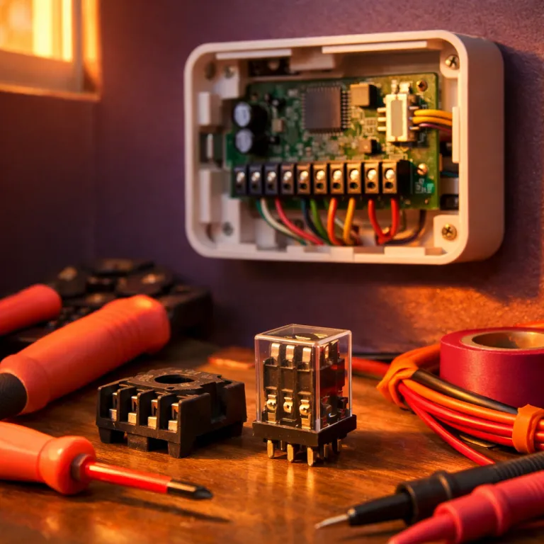
A smart thermostat quietly depends on precise relay hardware to manage heating and cooling. In many advanced models, a dpdt relay provides the flexible double pole and double throw architecture needed for complex control logic. This compact electromechanical switch routes power and current between circuits while keeping high voltage away from delicate electronics.
At its core, a relay uses an electromagnetic coil to move internal contacts between terminals. When the relay coil is energized at the correct coil voltage, the double pole contacts change throw position and redirect power to the selected circuit. In a dpdt relay, each pole throw pair can manage separate loads, which is ideal for switching between heating and cooling modes in a smart thermostat circuit.
Manufacturers design these relays to handle high power while remaining safe and compact. A dpdt power relay inside a thermostat often includes a led indicator or external indicator light on a relay module to show its status. This visual indicator reassures technicians that the relay dpdt is energizing correctly and that the relay high current path is functioning as intended.
Compared with a simpler spdt relay, the dpdt switch structure offers more versatile control. Two independent pole double paths allow the thermostat to manage both a fan motor and a compressor motor using coordinated double throw relay actions. For homeowners, this means smoother transitions, fewer misfires, and more reliable comfort control from modern smart thermostat products.
How dpdt relays interface with low voltage smart thermostat electronics
Smart thermostats operate with low control voltage, yet they must command equipment that draws substantial current. The dpdt relay acts as a protective barrier, allowing low voltage electronics to control high power loads without direct electrical contact. Inside the thermostat, the relay coil connects to the control board, while the power relay contacts connect to the heating and cooling circuits.
When the thermostat logic decides to start heating, it energizes the relay coil at the specified coil voltage. This action moves the double pole contacts from one throw position to the other, sending power through the correct terminals toward the furnace or heat pump motor. The same dpdt relay can then reverse its pole throw configuration to start cooling, using the alternate double throw path.
Many premium smart thermostat products mount their relays on a din rail within the equipment cabinet. A din rail installation keeps multiple relays organized, especially when several dpdt power devices and an occasional spdt relay share the same control panel. Some relay module designs add a led indicator or full led indicator light bar to show which throw relay is active at any moment.
For readers wanting deeper context on how advanced thermostats optimize compressor cycles, a detailed guide on Nest Airwave technology benefits explains how control algorithms interact with relay hardware. In every case, the dpdt switch and its associated relay dpdt wiring must be correctly sized for voltage dpdt ratings and relay high current demands. Properly matched coil voltage and power ratings prevent overheating, nuisance trips, and premature relay failures.
Managing high power HVAC loads with dpdt relay configurations
Heating and cooling systems often involve inductive loads such as compressor and blower motors. A dpdt relay is well suited to manage these high power devices because its double pole contacts can separate different current paths. One pole double path might control the compressor motor, while the other double throw path manages the indoor fan or auxiliary heater.
In many smart thermostat installations, the dpdt power relay is mounted near the air handler rather than inside the wall unit. The thermostat sends a low voltage control signal to the relay coil, which then switches mains power through the appropriate terminals. This separation keeps the thermostat electronics safe while the relay high contacts handle the demanding current of the HVAC circuit.
Installers must pay close attention to screw terminals and wiring quality when connecting these relays. Loose screw connections on a dpdt relay or spdt relay can cause arcing, heat buildup, and intermittent faults that confuse the thermostat control logic. A relay module with clear indicator light features and labeled terminals helps technicians verify each pole throw path during commissioning.
For homeowners evaluating equipment choices, an overview of American Standard thermostat benefits illustrates how reputable products integrate robust relay dpdt designs. Whether the system uses a single throw relay or multiple dpdt switch units, the goal remains consistent and safe power delivery. Correctly specified coil voltage, adequate contact ratings, and reliable din rail mounting all contribute to long term smart thermostat performance.
Safety, isolation, and indicator design in thermostat relay modules
Electrical safety is a central concern whenever a smart thermostat controls mains powered equipment. The dpdt relay provides galvanic isolation between the low voltage control electronics and the high power HVAC circuit. This isolation ensures that faults on the load side do not feed dangerous voltage back into the thermostat or connected home network.
Within a relay module, the relay coil and contact terminals are physically separated, and insulation distances are carefully engineered. When the coil voltage energizes the dpdt relay, only the mechanical linkage moves, while the control side remains electrically isolated. This design allows a small dpdt switch signal to manage a much larger power relay function without compromising user safety.
Visual feedback further enhances safety and diagnostics for technicians and informed homeowners. Many modern relays include a led indicator or external indicator light that shows when the relay dpdt is energized and which throw relay path is active. In multi stage systems, several relays may line up on a din rail, each with its own led indicator to identify the active pole double configuration.
Compared with older installations that relied on silent, hidden relays, these products make troubleshooting more transparent. A failed relay coil, incorrect coil voltage, or stuck pole throw contact becomes easier to identify when the led indicator does not match the expected thermostat command. Whether the system uses a dpdt power relay or a simpler spdt relay, clear labeling of screw terminals and consistent indicator design significantly reduce maintenance time.
Integrating dpdt relays into complex smart thermostat circuits
Modern smart thermostats often coordinate multiple HVAC components, ventilation systems, and sometimes auxiliary devices. In such scenarios, several dpdt relay units may work together to route power and current through different circuit branches. Each relay dpdt manages its own double pole and double throw configuration, yet all respond to a unified control strategy.
For example, one dpdt power relay might handle the main compressor motor, while another controls an auxiliary heater and circulation pump. The thermostat energizes each relay coil at the appropriate coil voltage, sequencing pole throw changes to avoid inrush surges and equipment conflicts. When designed correctly, this network of relays and terminals delivers smooth transitions between modes and protects motors from rapid cycling.
Control boards frequently combine dpdt switch outputs with occasional spdt relay outputs for simpler tasks. A relay module mounted on a din rail can host both relay types, each with its own led indicator or indicator light. Clear labeling of voltage dpdt ratings, screw terminals, and power relay capacities helps installers match each throw relay to its intended load.
Readers who want to understand how documentation supports such complexity can consult a detailed guide on using a Honeywell Pro Series thermostat manual. That kind of manual explains how products specify coil voltage, relay high current limits, and acceptable circuit configurations. When all dpdt relays and spdt relay units are correctly integrated, the smart thermostat can safely orchestrate high power equipment with consumer friendly simplicity.
Practical selection tips for dpdt relays in smart thermostat projects
Choosing the right dpdt relay for a smart thermostat project requires more than matching physical size. The relay coil must be rated for the thermostat’s control voltage, and the contacts must handle the expected power and current. Undersized contacts or incorrect coil voltage can lead to overheating, chatter, or premature failure of the relay dpdt.
Start by identifying whether the application needs a dpdt power relay or a lighter duty signal relay. High power compressor or fan motor loads demand generous pole double ratings and robust screw terminals, while small accessory circuits may work with a compact spdt relay. Always verify voltage dpdt specifications, maximum current, and the type of circuit being switched, especially with inductive motors.
Installation environment also influences product choice, particularly in equipment rooms or outdoor enclosures. A relay module designed for din rail mounting can simplify wiring and future expansion when multiple relays share the same panel. Look for models with a clear led indicator or indicator light so technicians can confirm which throw relay path is active without test instruments.
Smart thermostat enthusiasts should also consider long term serviceability when selecting products. Relays with standardized terminals, accessible screw connections, and clear pole throw diagrams reduce confusion during upgrades or repairs. Whether you are specifying a single dpdt switch or coordinating several dpdt relays and spdt relay units, careful attention to ratings and layout ensures safe, reliable control of modern HVAC systems.
Key statistics on relay use in smart thermostat and HVAC control
- Percentage of residential HVAC systems that rely on electromechanical relays for primary equipment switching.
- Typical current rating range for dpdt power relay contacts used in domestic heating and cooling circuits.
- Average service life, in number of mechanical operations, for a relay dpdt operating within its specified coil voltage and load limits.
- Proportion of smart thermostat failures traced to wiring or terminal issues around relays rather than to the thermostat electronics themselves.
- Estimated reduction in maintenance time when relay modules include a led indicator or indicator light for each pole throw path.
Common questions about dpdt relays in smart thermostat applications
How does a dpdt relay differ from a spdt relay in thermostats ?
A dpdt relay provides two separate pole double paths, while a spdt relay offers only one. This means a dpdt switch can control two circuits or two aspects of one system, such as heating and cooling, using its double throw contacts. In smart thermostat circuits, the extra flexibility of dpdt relays supports more complex control strategies without adding separate control boards.
Why is coil voltage so important when selecting a dpdt relay ?
The relay coil must match the thermostat’s control voltage to energize reliably and safely. If the coil voltage is too low, the dpdt relay may chatter or fail to pull in, while excessive voltage can overheat and damage the coil. Correct coil voltage ensures stable operation of the relay dpdt and protects both the thermostat electronics and the connected HVAC equipment.
Can a dpdt relay handle high power compressor and fan loads ?
Many dpdt power relay models are specifically rated for high power inductive loads such as compressors and blower motors. Installers must check the current and voltage dpdt ratings, as well as the type of circuit, before using a relay high contact set for these applications. When properly specified, the double pole and double throw structure safely routes power through separate terminals for each motor.
Why do some relay modules include a led indicator or indicator light ?
A led indicator on a relay module provides immediate visual confirmation that the relay coil is energized. In complex panels with multiple dpdt relays and spdt relay units on a din rail, these lights help technicians identify which throw relay is active. This reduces troubleshooting time and makes it easier to verify that the thermostat control signals are reaching the correct pole throw contacts.
Are dpdt relays necessary for every smart thermostat installation ?
Not every system requires a dpdt relay, because some simple single stage furnaces work well with a spdt relay. However, multi stage equipment, heat pumps, or systems that share components often benefit from the flexibility of double pole and double throw contacts. In such cases, using a properly rated dpdt relay or dpdt power relay improves control options and supports future system upgrades.
References : ASHRAE, IEC standards for low voltage switchgear, and IEEE publications on electromechanical relay reliability.