Why a smart thermostat wiring check starts before you shop
A smart thermostat wiring check should begin before you even open a shopping tab. When homeowners skip that early look at the existing thermostat and the conductors attached behind it, they often end up with a shiny new smart thermostat that is not system compatible with their current heating and cooling setup. Many avoidable returns come from people who assume every thermostat wire is identical and that every hvac system behaves like a simple furnace.
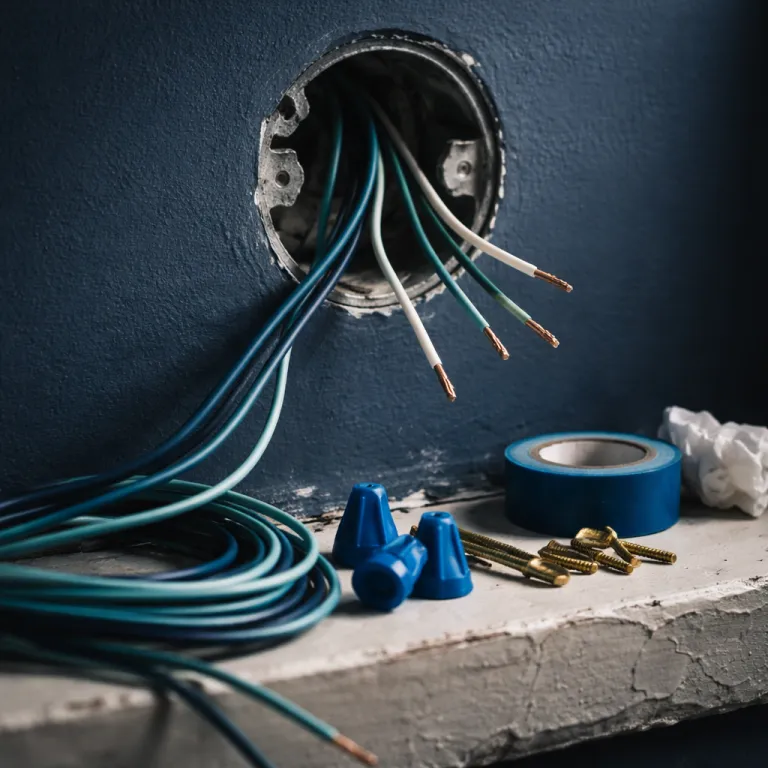
Start with safety and turn off power to the heating system at the breaker, because the low voltage wiring can still short and damage a control board if a bare wire touches the wrong terminal. Once the power is off, gently pull the attached thermostat straight toward you so the thermostat wires slide out without straining the wire connections or loosening the terminals on the wall plate. You want the current thermostat hanging just far enough that every wire labeled at the terminal strip is visible and every color can be matched to its letter.
Now take a straight on photo that shows the full thermostat wiring pattern, including any jumper between Rh and Rc, because that image becomes your roadmap for choosing a compatible smart thermostat later. Make sure the labels printed on the plastic next to each terminal are readable, since those tiny letters tell you whether your system is a single stage heat system, a heat pump system, or a more complex multi stage hvac system. That one clear photo lets you learn what each thermostat wire does without guessing, and it is the same photo a local professional will ask for if you contact local support or try to find pro help online.

Quick pre-shopping wiring checklist
- Shut off power to the hvac equipment at the breaker panel.
- Pull the thermostat straight out until all conductors and terminal labels are visible.
- Confirm you see thin low voltage wires, not thick 120 V or 240 V cable.
- Take a clear, straight on photo of the terminal strip, including any Rh–Rc jumper.
- Count how many thermostat wires are attached and note each terminal letter.
- Keep that photo handy when you compare smart thermostat compatibility charts.
Reading the wire labels like a pro
Once you have that photo, the next step in a smart thermostat wiring check is decoding the letters and colors. On many thermostats you will see a red thermostat wire on the R or Rh terminal for power, a white wire on W for heat, a yellow wire on Y for cooling, and a green wire on G for the fan control, although colors are not guaranteed. The common wire, usually labeled C, is the extra conductor that carries return power so a smart thermostat can stay lit and connected to Wi Fi without stealing power from the heating cooling cycle.
Heat pump systems add another twist with an O or B terminal that controls the reversing valve, and this is where many smart thermostat buyers get into trouble. Some heat pump manufacturers use the O terminal for cooling mode and others use the B terminal for heating mode, so you must learn which convention your pump follows before you move any thermostat wires. If you see both O and B wires attached or a single wire labeled O/B, that is a strong sign you have a heat pump system and you should double check that any new thermostat is explicitly compatible with heat pump and auxiliary heat control.
Look for extra labels like W2 or Y2, which indicate second stage heating or cooling and usually mean a more advanced hvac system that needs a thermostat with multi stage support. If you only see two thermostat wires, often R and W, you probably have a very simple heating only system where many smart thermostats will struggle without a common wire or an add on power kit. When the wiring looks crowded, with five or more wires attached and maybe a separate control board in a nearby panel, that is the moment to contact local service and find pro guidance instead of guessing which wire controls which part of the system.

Red flags that your system is not a match
Not every smart thermostat wiring check ends with a green light, and recognizing red flags early saves money and frustration. If you remove the attached thermostat and see only two thin thermostat wires on a basic mechanical dial, you are probably looking at a simple boiler or furnace control that lacks a common wire and may need a professional to add one at the control board. Many smart thermostats can fake a common connection, but that workaround can cause nuisance cycling, relay chatter, or even damage in older systems.
Another major warning sign is any mention of 120 V or 240 V on the thermostat base or the wires attached to it, because that means you have a line voltage system used for electric baseboard heating rather than a low voltage hvac system. Mainstream smart thermostats from brands like Google Nest, Ecobee, and Honeywell Home are not compatible with those high voltage systems, and forcing them onto line voltage wiring is unsafe. If your current thermostat has thick conductors in a cable that looks like house power wiring instead of the thinner thermostat wire bundle, stop immediately and contact local electricians or a local professional who handles line voltage controls.
Proprietary connectors are another dead end for DIY upgrades, especially on some Mitsubishi or LG mini split systems where a plug style cable replaces individual thermostat wires. Those systems use their own control logic and do not expose standard R, C, W, Y, and G terminals, so a conventional smart thermostat cannot talk to them directly. When you see unusual plugs instead of a common terminal strip, the only realistic path is to find pro support or use the manufacturer’s own smart controls rather than trying to force compatibility where the system was never designed for it.
Decision tree: what your wiring allows you to buy
A careful smart thermostat wiring check turns that messy bundle of wires into a simple decision tree. If your photo shows R, C, W, Y, and G thermostat wires on a single stage gas furnace with central air, almost every mainstream smart thermostat will be system compatible and you can shop based on features, price, and app design. In that scenario the common wire already provides stable power, the wire connections are straightforward, and you can focus on whether you prefer a learning style smart thermostat or a more manual schedule based model.
When you see a heat pump with O/B, Y, G, R, C, and maybe Aux or E for emergency heat, you need a thermostat that explicitly supports heat pump systems with auxiliary heating. Models like the Ecobee Smart Thermostat and Google Nest Learning Thermostat are designed for these setups, but only if you configure the heat pump orientation correctly so the O or B terminal energizes in the right mode. If you mis assign that single wire, the system may blow cold air when you call for heat or run the pump against the grain, which wastes energy and stresses the equipment.
Dual fuel systems, where a heat pump works alongside a gas furnace, raise the stakes again and are where I strongly recommend you find pro help. These setups often use extra thermostat wires for outdoor temperature sensors or special control board logic, and a wrong connection can leave either the pump or the furnace stranded. Any time your current thermostat has more than six wires attached, or you see zone panels with multiple bundles of thermostat wire feeding different areas, treat that as your signal to contact local experts instead of relying on guesswork.
| Visible thermostat terminals | Typical system type | Smart thermostat compatibility notes |
|---|---|---|
| R, W | Basic heat only furnace or boiler | Often needs a new C wire or power adapter kit for reliable smart thermostat power. |
| R, W, Y, G (no C) | Single stage furnace with A/C, no common | Many smart models require either a C wire run or a manufacturer supplied power extender. |
| R, C, W, Y, G | Single stage gas furnace with central air | Compatible with most mainstream smart thermostats when the control board is 24 V. |
| R, C, Y, G, O/B, Aux or E | Heat pump with auxiliary or emergency heat | Requires a smart thermostat that supports heat pump and aux heat configuration. |
| R, C, W1, W2 or Y1, Y2 | Two stage heating or cooling | Needs a multi stage capable thermostat; confirm manufacturer compatibility charts. |
| Thick 120 V or 240 V conductors, no R/C/W/Y/G | Line voltage baseboard or radiant electric heat | Not compatible with standard low voltage smart thermostats; use line voltage controls instead. |
When to call a professional and how to prepare
A smart thermostat wiring check is meant to empower you, not turn you into an unpaid hvac system engineer. There is a clear line where a homeowner can safely handle labeling each thermostat wire and moving it to a new base, and where a local professional should take over and protect both your comfort and your equipment. If you feel unsure when you look at the control board, see more than one pump or multiple heating systems tied together, or cannot confidently match each wire labeled on the old thermostat to a terminal on the new one, that is the right time to find pro support.
Before you contact local service, gather the essentials so the technician can give precise advice without a site visit. Keep your straight on photo of the current thermostat wiring handy, plus a second photo of any furnace or air handler control board where the thermostat wires land, because those images show how the systems are actually wired. Note whether you have a heat pump outside, a gas or oil furnace inside, or a boiler with radiators, since that mix determines whether a given smart thermostat is compatible with your heating cooling needs.
When you talk to a professional, ask them to confirm which wire controls each function and whether a new common wire can be pulled if you are missing one. A good installer will also check that the power to the hvac system is correctly fused and that no bare wires attached to the terminals can short, which protects your investment in both the thermostat and the equipment. In the end, the smartest upgrade is not the sleekest app interface, but the thermostat wiring that quietly works every cold February night while you only notice the lower gas bill.
Key statistics for smart thermostat wiring and compatibility
- About 40 % of homes in the United States do not have a dedicated common wire at the thermostat, according to manufacturer surveys summarized in Sensi / Copeland technical support documentation on C wire prevalence and smart thermostat compatibility, which directly affects smart thermostat power requirements and often requires either a power adapter kit or a new cable run. This figure is based on aggregated service data rather than a government census.
- Heat pump manufacturers do not follow a single standard for the O/B reversing valve wire, with some brands energizing O for cooling and others energizing B for heating, which makes correct thermostat configuration critical after installation and is highlighted in many OEM wiring diagrams and installer guides for residential heat pump systems.
- Line voltage heating systems that operate at 120 V or 240 V, such as many electric baseboard heaters, are fundamentally incompatible with most low voltage smart thermostats designed for 24 V hvac systems, a distinction emphasized in U.S. Department of Energy consumer guidance on thermostats and residential controls for space heating and cooling.
- Dual fuel setups that combine a heat pump with a gas furnace require thermostats that can manage auxiliary and emergency heat stages, and mis wiring these systems can significantly reduce efficiency and comfort, as noted in Air Conditioning Contractors of America (ACCA) best practice manuals and training materials on residential equipment control strategies.
Frequently asked questions about smart thermostat wiring checks
How do I know if my system can support a smart thermostat ?
Check behind your current thermostat for a bundle of thin low voltage wires on labeled terminals such as R, C, W, Y, and G, then confirm that your furnace or air handler uses a 24 V control board rather than 120 V or 240 V line voltage. If you see a common wire on the C terminal and at least four other thermostat wires, most mainstream smart thermostats will be compatible with your hvac system. When in doubt, compare your wiring photo to the compatibility charts from major thermostat brands or send it to a local professional for confirmation.
What if I do not have a common wire at the thermostat ?
If your smart thermostat wiring check shows no wire on the C terminal, you still have options but need to be careful. Some smart thermostats include a power extender kit that connects at the furnace control board and effectively creates a common wire without running new cable. In older or more complex systems, the most reliable solution is to have a professional pull a new thermostat wire bundle so the thermostat has a dedicated common wire for stable power.
Can I install a smart thermostat on a heat pump system myself ?
Many homeowners can handle a basic heat pump swap if the wiring is straightforward and clearly labeled, but the O/B reversing valve setting must be configured correctly. During your smart thermostat wiring check, note whether the existing thermostat uses O, B, or a combined O/B terminal and how the system behaves in heating and cooling modes. If you see extra wires for auxiliary or emergency heat or a dual fuel setup with a furnace, it is safer to find pro help so the pump and backup heat are controlled properly.
What are the signs that I should not DIY my thermostat wiring ?
Stop and call a professional if you see thick 120 V or 240 V wires, proprietary plugs instead of individual terminals, more than six thermostat wires on complex zone panels, or any wiring that does not match standard R, C, W, Y, G, and O/B patterns. Those signs point to line voltage systems, mini splits, or advanced multi zone controls where a mistake can be expensive. A quick consultation with a local professional is far cheaper than replacing a damaged control board or misconfigured heat pump.
Why does everyone say to take a photo before removing any wires ?
The photo you take during a smart thermostat wiring check is your safety net and your wiring diagram. It records exactly where each thermostat wire was attached on the old thermostat, which makes it easy to move each conductor to the matching terminal on the new base. That same image also helps manufacturers and technicians verify compatibility, so you avoid guesswork and reduce the risk of mis wiring your hvac system.
References
- Sensi / Copeland technical support documentation on thermostat C wire prevalence and smart thermostat compatibility, based on internal manufacturer survey data and field service reports.
- U.S. Department of Energy consumer guidance on programmable and smart thermostats for residential hvac systems, including distinctions between low voltage and line voltage controls and recommended installation practices.
- Air Conditioning Contractors of America (ACCA) best practice manuals for residential thermostat wiring, dual fuel configuration, and equipment control recommendations used in contractor training.